BIM LOD guide · Level of DevelopmentHow much can you trust the model?
When we scan your building, the LOD you choose decides what we model and what you can safely do with it: a rough layout, measured member sizes for load calcs, or connection detail a fabricator can work from.
Size, shape, location, orientation and count all become specific, so you can measure from the model.
What you can rely onSizes and positions you can measure, within system tolerances.
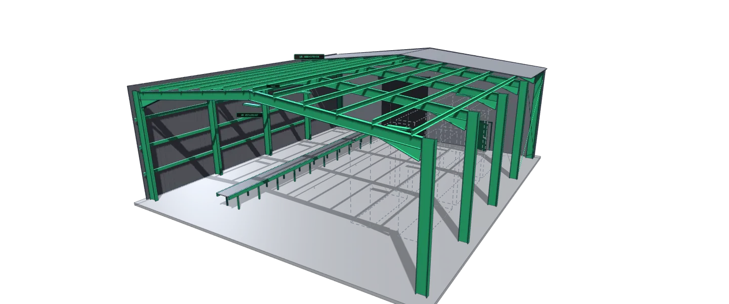
Exposed columns and rafters at their measured section sizes (tags shown), with haunches, purlins, girts and wall bracing, plus the conveyor, lights and sprinklers. Engineering grade.
Technical criteria
The VDCForum / BIMForum Global LOD Specification rates each element on five characteristics. The weakest one sets its level.
QuantitySpecific
SizeSpecific
ShapeSpecific
LocationSpecific
OrientationSpecific
Use it for
Design coordination
Construction documents
Accurate quantities
Measuring from the model
Not for
Fabrication
Trade-level clash resolution (connections & hangers aren't there yet)
Measure from the model?
Yes, within system tolerances
From a scan
Each exposed member is modelled at its measured size and position, and its visible profile is matched to a standard steel section. Uncertain matches are flagged for engineering review. This is the level you need for structural load calcs and checks.
In the specification
LOD 300, Specific: Modelled specifically within the project's tolerances for its system in ALL of: quantity, size, shape, location AND orientation.
LOD 500 Need an as-built? We provide georeferenced as-built models on request, verified against the scan. The package you choose still sets the detail inside it.
ScopeWe scan and model what is visible. Concealed elements, such as services and ducts above ceiling boards or anything behind finishes, must be specified in the scope so we can arrange access (for example, lifting ceiling tiles) or add a GPR survey. Check an item hidden from the scanner
Packages
Three ways to model your building
Almost every scan request falls into one of these. They map directly to levels in the VDCForum / BIMForum Global LOD Specification, so your engineer, contractor and fabricator all read the same thing.
LOD 200
Layout
Rough conceptual layout
Space planning, fit-out concepts, layout drawings, presentations.
You get
Walls, floors, roofs, openings
Main columns & beams as generic shapes
The overall layout and levels, approximately
Not included
Steel section sizes
Anything you'd calculate or fabricate from
Typically for Architects, space planners, facility managers
LOD 500: georeferenced as-built on request
LOD 300
Engineering
Accurate, sized members
Load calcs, structural checks, adding new loads (solar, plant, cranes, racking), design of alterations.
You get
Exposed structural members at measured size
Visible profiles matched to standard sections (UB, UC, PFC, angles…)
True positions, elevations, spans & orientation
Hidden or one-sided elements flagged at LOD 250
We model exposed members at measured positions and match visible profiles to standard sections. Uncertain matches are flagged for engineering review.
Not included
Connection detail (plates, bolts, welds)
Typically for Structural engineers, designers, insurers
LOD 500: georeferenced as-built on request
LOD 350 to 400
Fabrication
Connections & fabrication detail
Shop drawings, detailing new steel against the surveyed interfaces, retrofit connections, clash checks before installation.
You get
Everything in Engineering
Base plates, end plates, gussets, cleats, stiffeners (350)
Visible bolts, welds & plate thicknesses (400)
Interfaces where new steel will connect
Not included
Concealed items we can't see (e.g. cast-in anchors, encased steel) unless exposed
Typically for Steel detailers, fabricators, contractors
LOD 500: georeferenced as-built on request
See it in 3D:
Drawings Need drawings as well as the model? We also develop any model into a full drawing set on request: plans, sections, elevations and details, at whichever LOD you choose. See example drawings ↓
Drawings on request
From model to drawings
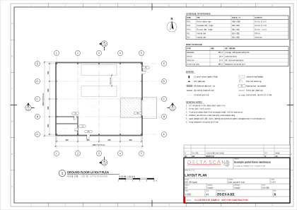
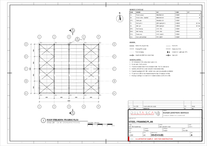
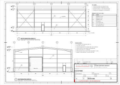
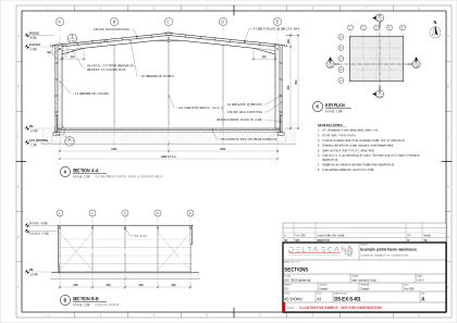
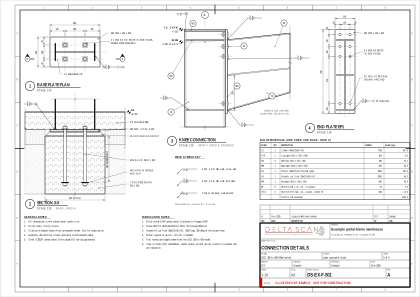
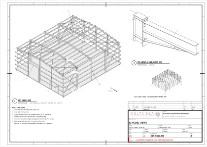
We develop any model into a full drawing set on request. Examples below are illustrative.
Layout planLayoutLOD 200DS-EX-A-101
Steel framing planEngineeringLOD 300DS-EX-S-201
ElevationsEngineeringLOD 300DS-EX-S-301
SectionsEngineeringLOD 300DS-EX-S-401
Connection detailsFabricationLOD 350 to 400DS-EX-F-501
3D model viewsAny packageAny LODDS-EX-M-601
Every sheet shown is an illustrative sample of the guide's example warehouse, not for construction. Select a sheet to view it larger.
Check an item
Doors, valves, sprinklers, rebar… is it in the model?
Find any item to see how it's modelled in each package. Dashes mean it's not modelled. Anything a laser scanner physically can't see is listed under Hidden from the scanner, with how a GPR survey can add it.
Item
Layout
Engineering
Fabrication
Notes
Walls & partitions
LOD 200
LOD 250
LOD 250
Faces as scanned. Studs, insulation and services inside aren't visible.
Doors (leaf, frame, swing)
LOD 200
LOD 300
LOD 300
Layout: an opening. Engineering: door size, type, swing and head height.
Door handles & ironmongery
Not modelled
Not modelled
Not modelled
Not modelled by default. We can add them as components or record them as data on request.
Windows & openings
LOD 200
LOD 300
LOD 300
Opening size, sill and head heights. Frame profiles simplified.
Curtain wall & glazing
LOD 200
LOD 300
LOD 350
Mullion grid at 300; mullion profiles and brackets at 350 if visible.
Ceilings & bulkheads
LOD 200
LOD 250
LOD 250
Heights and bulkheads. Grid layout on request. The void above needs ceiling tiles lifted to scan.
Floors, stairs & ramps
LOD 200
LOD 300
LOD 350
Steel stairs reach 350 with stringer connections.
Handrails & balustrades
LOD 200
LOD 300
LOD 400
Fabrication level includes posts, base plates and fixings.
Toilets & sanitary fixtures
LOD 200
LOD 300
LOD 300
Type and position (WC, basin, urinal). Generic manufacturer-neutral objects.
Built-in joinery & counters
LOD 200
LOD 250
LOD 250
Envelope and position. Internal shelving isn't modelled.
Furniture, stock & loose items
Not modelled
Not modelled
Not modelled
Excluded by default. They move, so they don't belong in an as-built model.
Finishes, paint & signage
Not modelled
Not modelled
Not modelled
Not modelled as geometry. Can be recorded as data or photo references.
StructureSteel columns & beams
LOD 200
LOD 300
LOD 350 to 400
Engineering: measured and matched to standard sections for load calcs. Uncertain matches are flagged for engineering review.
StructureBracing, purlins & girts
Not modelled
LOD 300
LOD 350 to 400
Secondary steel is left out of Layout, sized at Engineering.
StructureBase plates, end plates, gussets
Not modelled
Not modelled
LOD 350
Positions and plate sizes as they exist on site.
StructureBolts, nuts & welds
Not modelled
Not modelled
LOD 400
Visible bolt groups and weld runs. Embedded anchor length is unknown.
StructureConcrete columns, beams & walls
LOD 200
LOD 250
LOD 250
Outer faces only. Reinforcement inside needs GPR.
StructureFloor & roof slabs
LOD 200
LOD 250
LOD 250
Top and soffit where both are visible. Thickness confirmed at edges or by GPR/coring.
StructureRoof sheeting & wall cladding
LOD 200
LOD 250
LOD 250
Profile and extent. The fixings behind aren't visible.
StructureCrane rails & runway beams
LOD 200
LOD 300
LOD 350
Rail alignment and levels at 300. Brackets and stops at 350.
StructureMezzanines & platforms
LOD 200
LOD 300
LOD 350 to 400
Frame, decking and connections as for main steel.
Services & fireDuctwork
LOD 200
LOD 300
LOD 350 to 400
Mains and visible branches. Hangers at 350; flanges and fixings at 400.
Services & fireCable trays & ladders
LOD 200
LOD 300
LOD 350
Tray width, height and route. Supports at 350. Cable content is not modelled.
Services & fireExposed conduit (≥ 50 mm)
Not modelled
LOD 250
LOD 300
Smaller conduit is excluded unless requested.
Services & fireService pipework (water, gas, air)
LOD 200
LOD 300
LOD 350 to 400
Nominal size, route and valves. Insulated pipe is modelled to the insulation face.
Services & fireSprinkler mains & branches
LOD 200
LOD 300
LOD 350
Pipe sizes and routes. Hangers at 350.
Services & fireSprinkler heads
Not modelled
LOD 300
LOD 300
Position and orientation (pendant/upright).
Services & fireLighting fixtures
LOD 200
LOD 300
LOD 300
Type and position. Wiring above the ceiling is not visible.
Services & fireHVAC plant (AHUs, RTUs, chillers)
LOD 200
LOD 250
LOD 300
Overall envelope at 250. Connection points and plinths at 300.
Services & fireElectrical panels & DBs
LOD 200
LOD 250
LOD 300
Envelope and clearance zone in front. Internals not modelled.
Process & industrialProcess piping
LOD 200
LOD 300
LOD 350 to 400
Nominal sizes (DN) with flanged joints at 300, gaskets at 350, stud bolts and welds at 400.
Process & industrialValves & fittings
Not modelled
LOD 300
LOD 350 to 400
Type, position and handwheel orientation. Flange bolting at 400.
Process & industrialPumps & motors
LOD 200
LOD 300
LOD 400
Nozzles and baseplate at 300. Hold-down bolts at 400.
Process & industrialTanks & vessels
LOD 200
LOD 250
LOD 300
Shell within ±2″. Nozzles, legs and anchor plates at 300+.
Process & industrialConveyors
LOD 200
LOD 300
LOD 350
Path and envelope at Layout. Frame, belt width and supports at 300. Drives and connections at 350.
Process & industrialMachinery & production lines
LOD 200
LOD 250
LOD 300
Bounding envelope plus critical interfaces. Internal mechanisms are never modelled.
Process & industrialPipe racks & supports
LOD 200
LOD 300
LOD 350 to 400
Shoes at 300, guides and clamps at 350, welds and bolts at 400.
Process & industrialSmall-bore pipe, tubing & instruments
Not modelled
Not modelled
LOD 300
Excluded by default. Can be added for specific areas.
Site & externalGround levels & terrain
LOD 200
LOD 250
LOD 250
Surface from point cloud. Accuracy depends on vegetation cover.
Site & externalRoads, kerbs & paving
LOD 200
LOD 250
LOD 250
Edges and levels. Pavement build-up is not visible.
Site & externalManholes, pits & covers
LOD 200
LOD 250
LOD 250
Cover position and level. Inverts only if the chamber is opened and scanned.
Site & externalFences, gates & bollards
LOD 200
LOD 300
LOD 300
Line, height and gate openings.
Hidden from the scannerUnderground pipes & cables
Not visible to laser scanGPR add-on · LOD 200 to 250
Located with GPR and utility tracing, then added to the model at approximate depth.
Hidden from the scannerRebar & post-tension tendons in slabs
Not visible to laser scanGPR add-on · LOD 200 to 250
GPR maps bar positions and spacing before coring or drilling. Cover depth is approximate.
Hidden from the scannerConduits & cables inside slabs
Not visible to laser scanGPR add-on · LOD 200 to 250
GPR can locate embedded conduits to help you plan cutting and coring.
Hidden from the scannerCables & pipes inside walls
Not visible to laser scanGPR add-on · LOD 200
Not visible to a laser scanner. Use drawings, GPR (wall-dependent) or opening-up works.
Hidden from the scannerSlab & wall thickness
Not visible to laser scanGPR add-on · LOD 250
Measured where an edge is exposed, otherwise estimated by GPR or confirmed by coring.
Hidden from the scannerStuds & build-up inside partitions
Not visible to laser scan
Not reliably captured by scan or GPR. Use drawings or intrusive survey.
Hidden from the scannerAbove-ceiling services (tiles in place)
Not visible to laser scan
Not visible with tiles in place. Specify it in the scope so ceiling tiles can be lifted during the scan.
Hidden from the scannerCast-in anchors & embedment depth
Not visible to laser scan
Only the exposed nut and thread are visible. Embedment comes from drawings or testing.
Nothing matches. Ask us, and we'll tell you how we'd capture it.
Build your scope
Which LOD do you need?
Answer four quick questions. We'll recommend a level for each part of your building, ready to send to us with a quote request or to copy into your own scope.
Your recommendationChoose a use and what you need modelled to see your recommendation.
Element group
Recommended LOD
Why
Need an as-built? We provide georeferenced LOD 500 as-built models on request, verified against the scan. The levels above set the detail inside it.
Need drawings? We also develop the model into a full drawing set on request: plans, sections, elevations and details.
We model what is visible. List any concealed elements you need, such as services and ducts above ceiling boards, in the scope so we can arrange access or a GPR survey.
LOD 250 tolerance: ±2″ (≈ 50 mm) unless noted otherwise. Tighter tolerances can be specified.
The whole scale, the rules behind it and the words people use. Open any section.
All LOD levels (000 to 500)
From “not modelled” to “as-built”. Select a level to see it in 3D.
The weakest-link test
Set how well each characteristic is known and see what level an element really is.
To be LOD 300, an element must be specific in all five characteristics. One weak link sets the level for the whole element.
Quantity
Size
Shape
Location
Orientation
LOD 300
All five are exact. It's genuinely LOD 300, so you can measure it and run calcs on it.
What a scanner can and can't see
Why some elements reach LOD 300 from a scan and others honestly stop at LOD 250.
A laser scanner measures millions of surface points. That's why some elements reach LOD 300 from a scan and others honestly stop at LOD 250. Anything concealed, such as services and ducts above ceiling boards, is only captured if it is specified in the scope and access is arranged before site day.
LiDAR + drone On complex sites and large scans we combine LiDAR scanning with drone mapping: the scanner captures interiors and structure in detail, the drone captures roofs, façades and the surrounding site, and we bring both together in one model of the whole site, inside and out.
LOD 250Walls, slabs, cladding. We see one face. The thickness and what's inside (studs, rebar, services) can't be confirmed without opening it up, so the honest level is LOD 250: faces within ±2″ (≈ 50 mm), or tighter if specified.LOD 300+Exposed steel. Scanned from several positions we capture flanges, web, depth and length. Then we match each visible profile to a standard section and flag uncertain matches for engineering review. That gives you LOD 300 for load calcs, and with visible connections, LOD 350/400.
Tip: need tighter than ±2″? The spec lets you state it, e.g. "LOD 250 at ±10 mm". Tolerances for scan accuracy are covered by VDCForum's companion LOA (Level of Acceptance) guidance.
Rules of thumb
LOD is about reliability, not prettiness, plus the ten rules of LOD.
The D stands for Development, not "Detail". A beautiful render can still be LOD 200 if you can't rely on its sizes. LOD tells you how far you can trust each element.
Per element, not per model
There's no such thing as an "LOD 300 model". Your steel might be at 300 while the walls sit at 250 and the furniture at 000. Mixing levels is normal, and it's how you keep costs sensible.
Higher is not always better
Modelling every bolt when you only need member sizes for a load calc costs time and money for nothing. The right LOD is the lowest one that does the job.
As-built (LOD 500) is about verification, not detail
LOD 500 means as-built: measured from what's really on site and verified against it. We provide georeferenced as-built models on request. You still choose how much detail goes into it: Layout (200), Engineering (300) or Fabrication (350 to 400).
The 10 rules of LOD
The rules recommended in the VDCForum / BIMForum Global LOD Specification, each paired with the misunderstanding it prevents.
01LOD belongs to elements, not whole models
Myth “Just send us an LOD 400 model.”
There's no such thing as an “LOD 300 model.” A model is a mix of elements at different levels. Ask for “the walls at LOD 300,” not “a 300 model.”
02LOD is not a project phase
Myth “Design development = LOD 300.”
At any phase some elements are ahead and some behind. If LOD always matched the phase, the term would be pointless.
03LOD 000 means “not in scope”
Myth “If it's not in the model, someone forgot it.”
A clean, contractual way to say an element class is excluded from a modeller's scope, and can't be inferred from a mass either.
04LOD 250 is optional, for early decisions & scans
Myth “It's either a rough placeholder or fully accurate.”
Quantity exact, surfaces within ±2″ unless noted otherwise. Built for early estimating, early coordination and scan-to-BIM.
05LOD 350 is for coordination between systems
Myth “300 is enough for clash detection.”
After elements are specific (300), the connections, supports and clearances get added so trades can coordinate before fabrication.
06Higher is NOT always better
Myth “Just model everything to 400 to be safe.”
The right LOD is the one your purpose needs. Modelling every screw for a simple clash check wastes time and money.
07Information needs go in the BIM Execution Plan
Myth “LOD tells me what data is attached.”
Non-graphic data (specs, manufacturer, cost…) is project-specific. Define it in the PEP/BEP; its reliability can differ from the geometry's.
08All 5 characteristics must pass: weakest link wins
Myth “Right size, roughly right place = 300.”
Quantity, size, shape, location, orientation. If even one is only approximate, the element is not LOD 300.
09Tolerances come from industry standards
Myth “The model says 3,047.62 mm so it must be exact.”
Everything in a computer is precise, but that doesn't make it accurate. From LOD 300 up, tolerances come from each material's fabrication & installation standards. LOD 250 uses ±2″.
10LOD 500 = as-built, verified on site
Myth “500 must be more detailed than 400.”
LOD 500 means the model is checked against reality. The amount of detail inside it still follows what you ordered: a scanned wall with a hidden core is as-built at 250 detail; exposed steel can be as-built at 300 to 400.
Glossary
LOD, LOA, UNO, BEP and the other terms you'll meet.
LOD
Level of Development: how far a model element has been developed, and how much you can rely on it. (Not “Level of Detail.”)
ME
Model Element: one object or system in the model, e.g. a column, a duct run, a wall.
MEA
Model Element Author: the party responsible for modelling a given element to a given LOD.
PEP / BEP
Project (BIM) Execution Plan: where the project defines which LOD each element reaches, when, by whom, and for what use.
MET / LOD Matrix
Model Element Table: the spreadsheet listing elements vs. phases and their required LOD.
NGI
Non-Graphic Information: data attached to elements (manufacturer, fire rating, cost…). Defined separately in the PEP.
UNO
Unless Noted Otherwise: e.g. LOD 250 is ±2″ UNO, so your project can tighten it.
LOA
Level of Acceptance / Accuracy: companion VDCForum guidance for reality capture & laser scanning tolerances.
Scan-to-BIM
Creating a model of existing conditions from laser scan (point cloud) data.
Tolerance
How far reality may differ from the model and still be acceptable.
We use cookies to measure how the site is used and to support our marketing. Accept these, or continue with only the essential cookies the site needs to run. See our Cookie Policy.